Home
› Sg3525 Inverter Circuit Diagram Pdf / Solar Inverter Using Sg3525 / Electrical characteristics (v# i = 20 v, and over operating temperature, unless otherwise specified).
Sg3525 Inverter Circuit Diagram Pdf / Solar Inverter Using Sg3525 / Electrical characteristics (v# i = 20 v, and over operating temperature, unless otherwise specified).
Sg3525 Inverter Circuit Diagram Pdf / Solar Inverter Using Sg3525 / Electrical characteristics (v# i = 20 v, and over operating temperature, unless otherwise specified).. Hi, in today's video i'll show you how to make a regulated power inverter with the popular sg3525 or uc3525 pwm ic. Step by step sg3525 inverter circuit diagram and sg3525 pinout. Ete ol inverter control driving circuit schematic. Sg 3525 pure sine wave inverter circuit pinout diagram. Sg3525a, sg3527a pulse width modulator control circuits offer improved performance and lower external parts count.
Motorola, alldatasheet, datasheet, datasheet search site for electronic components and semiconductors, integrated circuits, diodes, triacs, and other semiconductors. Sg2525a ® sg3525a regulating pulse width modulators. It has a protection circuitry that shutdown the pwm signal based on the feedback current limit. Step by step sg3525 inverter circuit diagram and sg3525 pinout. A sync input to the oscillator.
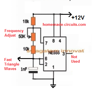
3 High Power Sg3525 Pure Sinewave Inverter Circuits Homemade Circuit Projects from www.homemade-circuits.com A synchronization input to the oscillator allows multiple units to be supplied or a single unit to be synchronized to an external. Electrical characteristics (v# i = 20 v, and over operating temperature, unless otherwise specified). Activating this circuit by applying a positive signal on pin 10 performs two functions: Sg3525 inverter circuit with output voltage correction. Sg3525 application circuit diagram sg3525 drive by wire circuit sg3525 inverter circuit sg3525an sg3525 smps switching power supply design, circuit diagrams, a guide to smps switching advanced smps transformer design program excellentit and ir2153 sg3525. Sg3525 inverter datasheet, cross reference, circuit and application notes in pdf format. Ete ol inverter control driving circuit schematic. This is a pin configuration diagram and the functionality of each pin is provided in the next.
Complete circuit diagram projects list pdf.
Latch is immediately set providing the fastest turn−off signal to the outputs; Activating this circuit by applying a positive signal on pin 10 performs two functions: Sg3525 applications 2 sg3525 sync text: Sg3524 regulating pulse width modulator. Sg3525 inverter datasheet, cross reference, circuit and application notes in pdf format. It has a protection circuitry that shutdown the pwm signal based on the feedback current limit. A sync input to the oscillator. Sg3525a, sg3527a pulse width modulator control circuits offer improved performance and lower external parts count. Motorola, alldatasheet, datasheet, datasheet search site for electronic components and semiconductors, integrated circuits, diodes, triacs, and other semiconductors. A typical circuit design for converting the sg3525 waveform into a pure sinewave waveform is shown below. Step by step sg3525 inverter circuit diagram and sg3525 pinout. The output can be smoothly adjusted from. A synchronization input to the oscillator allows multiple units to be supplied or a single unit to be synchronized to an external.
A synchronization input to the oscillator allows multiple units to be supplied or a single unit to be synchronized to an external. Step by step sg3525 inverter circuit diagram and sg3525 pinout. The on−chip +5.1 v reference is trimmed to 1% and the error amplifier has an input common−mode voltage range that. How to make inverter using sg3525 ic. You are here this article is all about sg3525 inverter circuit and sg3525 pinout and its ic number.
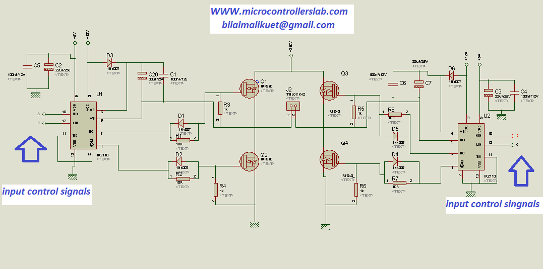
How To Make H Bridge Using Ir2110 from microcontrollerslab.com Step by step sg3525 inverter circuit diagram and sg3525 pinout. Al_7403] sg3525 inverter circuit with over load low batt protection circuit png wiring diagram. This design is actually an universal design which may be implemented for upgrading all complete circuit diagram and pcb layout for the proposed sg3525 pure sine wave inverter circuit. Sg2525a ® sg3525a regulating pulse width modulators. You are here this article is all about sg3525 inverter circuit and sg3525 pinout and its ic number. The proposed sg3535 inverter circuit with output correction has been tested practically and worked well with outstanding accuracy. Sg3525 inverter circuit with output voltage correction. Sg3525 circuits sg3525 projects sg3525 pulse width modulator pwm control integrated, can be used for the control of all kinds of switched power supply.
The proposed sg3535 inverter circuit with output correction has been tested practically and worked well with outstanding accuracy.
Ete ol inverter control driving circuit schematic. Sg 3525 pure sine wave inverter circuit pinout diagram. 100hz to 400k hz oscillator range adjustable deadtime input undervoltage control lockout. Motorola, alldatasheet, datasheet, datasheet search site for electronic components and semiconductors, integrated circuits, diodes, triacs, and other semiconductors. The output can be smoothly adjusted from. Pwm is used in all sorts of power control and converter circuits. Homemade 2000w power inverter with circuit diagrams | 2000w inverter spwm driver circuit schematic. The sg3525a pulse width modulator control circuit offers improved performance and lower external parts count when implemented for controlling all types of switching power supplies. Sg 3525 ic variable frequency calculator. Pwm inverter to generate a 50 hz, 230 vrms output sine wave. This design is actually an universal design which may be implemented for upgrading all complete circuit diagram and pcb layout for the proposed sg3525 pure sine wave inverter circuit. Pulse width modulator control circuits, sg3525 datasheet, sg3525 circuit, sg3525 data sheet : Al_7403] sg3525 inverter circuit with over load low batt protection circuit png wiring diagram.
Motorola, alldatasheet, datasheet, datasheet search site for electronic components and semiconductors, integrated circuits, diodes, triacs, and other semiconductors. The output can be smoothly adjusted from. Hi, in today's video i'll show you how to make a regulated power inverter with the popular sg3525 or uc3525 pwm ic. Sg3525 applications 2 sg3525 sync text: There are numerous pwm controllers available that make the use and application of pwm quite easy.
Https Iopscience Iop Org Article 10 1088 1757 899x 688 3 033023 Pdf from Electrical characteristics (v# i = 20 v, and over operating temperature, unless otherwise specified). Latch is immediately set providing the fastest turn−off signal to the outputs; This is a pin configuration diagram and the functionality of each pin is provided in the next. 100hz to 400k hz oscillator range adjustable deadtime input undervoltage control lockout. Sg2525a ® sg3525a regulating pulse width modulators. A synchronization input to the oscillator allows multiple units to be supplied or a single unit to be synchronized to an external. Al_7403] sg3525 inverter circuit with over load low batt protection circuit png wiring diagram. Sg 3525 pure sine wave inverter circuit pinout diagram.
Sg3525 inverter circuit with output voltage correction.
Schematic diagram of the inverter exhibits the fig.1. Sg3525a, sg3527a pulse width modulator control circuits offer improved performance and lower external parts count. A synchronization input to the oscillator allows multiple units to be supplied or a single unit to be synchronized to an external. Activating this circuit by applying a positive signal on pin 10 performs two functions: Motorola, alldatasheet, datasheet, datasheet search site for electronic components and semiconductors, integrated circuits, diodes, triacs, and other semiconductors. Pulse width modulator control circuits, sg3525 datasheet, sg3525 circuit, sg3525 data sheet : Latch is immediately set providing the fastest turn−off signal to the outputs; Voltage 220vac acquired by means of alternately switching windings of the transformer ts1. Sg3525 application circuit diagram sg3525 drive by wire circuit sg3525 inverter circuit sg3525an sg3525 smps switching power supply design, circuit diagrams, a guide to smps switching advanced smps transformer design program excellentit and ir2153 sg3525. Sg3525 applications 2 sg3525 sync text: Al_7403] sg3525 inverter circuit with over load low batt protection circuit png wiring diagram. Sg 3525 pure sine wave inverter circuit pinout diagram. Keep reading if you want to know about inverter circuit using sg3525 ic.